Limit Switches and Guard Locking
First published Winter of 2021.

Thomasnet.com
defines limit switches as switches “used to automatically detect or sense the
presence of an object or to monitor and indicate whether the movement limits of
that object have been exceeded. The original use for limit switches, as implied
by their name, was to define the limit or endpoint over which an object could
travel before being stopped. It was at this point that the switch was engaged
to control the limit of travel.”
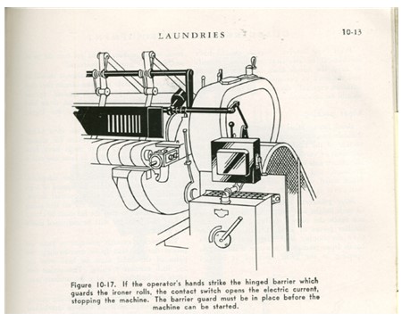
Limit switches have many applications, including common household applications such as a food processor that requires the lid to be on and the bowl locked on, automobiles requiring the transmission be placed in Park to start, coffee bean grinders with interlocks on the lid or collection compartment, an oven that turns off when the door is opened, a microwave that will not operate without the door closed, and certain automobiles that wouldn’t start without the seatbelt fastened. Limit switches are an integral part of machine safeguarding because they can determine when a guard has been removed or reinstalled.
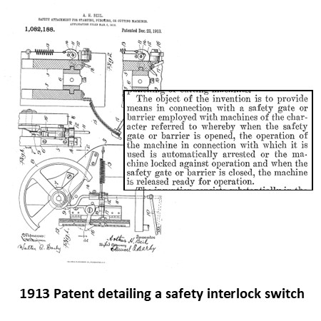
Sometimes, defendants raise the issue of state of the art. If it isn’t invented, it is not state of the art. If it is available somewhere on the commercial market, it is state of the art. If the objective can be achieved with combinations of components and this information is known, it is state of the art. Interlocks on guards are ancient technology. No one can make a claim that guarding and interlocking guards is something new. It is not. The patent shown on this page details an early form of interlocking from 1913. When a hazard cannot be eliminated through the design of a machine, the hazard must be guarded.
Careful consideration needs to be given to proper design and access to the system, since a guarding system that is difficult to use or access is more likely to be bypassed or removed, placing the operator or maintenance personnel in danger.

Guarding must prevent
dangerous motion during access to the hazard, which would be accomplished by
using interlock mechanisms described in this section. To be effective, an interlocking guard must
satisfy three requirements:
· It must guard the dangerous part
before the machine can be operated.
· It must stay closed until the
dangerous part is at rest.
· It must prevent operation of the
machine if the interlocking device fails.
These guards must be interlocked with the power source of the hazard to ensure that the power will be switched off whenever the guard mechanism is not properly in place. The power source itself, or control of the power source, is routed through an interlock switch on the guard itself. When the switch detects movement of the guard, it will isolate the power supply to the hazard, and machine movement will be prevented. The switches must also be “fail-safe”, such that if they fail, the power source will be safely isolated, preventing machine operation. The effectiveness of an interlock switch depends on its ability to withstand attempts to defeat the mechanism. Unfortunately, it is not uncommon to encounter interlocks that have been removed, taped down, or otherwise tampered with by maintenance personnel or operators who require frequent access to machine parts behind the guarding. Depending on the risk involved, switches may be designed to resist impulsive tampering, or they may be designed to be virtually impossible to defeat.


If a guard is the best
possible solution to protect the user it is imperative that the guard be
designed in such a way as to remain in place if at all possible. This requires the manufacturer to insure that
the guard is designed, manufactured,
and installed in such a way as to insure permanent reliability. If a guard is made to be easily removable for
cleaning, maintenance, or other functions, it must be interlocked to prevent hazardous machinery from being
operated with the guard removed. Suited to machines with run-down
characteristics, interlocks can be can be designed to prevent opening a guard
until it is safe to do so, either through mechanical time delay switches or
through a control circuit which locks the guard shut.

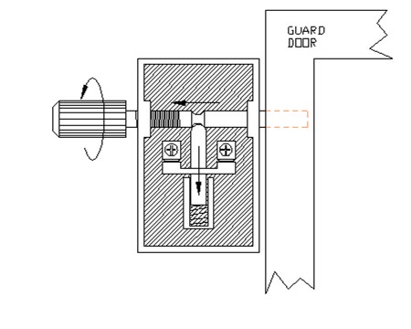
Time Delay Bolt Switch
The time delay bolt switch
shown here is an example of a mechanical delay system. While there are higher tech designs that
ensure the machine is stopped before allowing the guard to be opened, this
historical method of guard locking can still have applications today. The first few turns of the operating knob
opens the contacts and shuts down the machine, but the guard locking bolt is
not fully withdrawn until the knob is turned many more revolutions, allowing a
machine run-down time of up to 20 seconds.
This interlock must be designed such that it is only possible to extend
the locking bolt when the guard is fully closed.

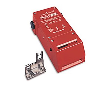
Allen Bradley Guard Locking Interlock
This Allen-Bradley modern guard locking safety interlock found on rockwellautomation.com is an example of a safety interlock that can be integrated with a PLC (Programable Logic Controller) which is essentially a computer that controls machine function including safeguards, that can ensure a machine is fully stopped prior to allowing machine access. The latch is a key that is part of the guard that inserts into the switch, and the switch will keep it locked preventing machine access, until the programmed criteria are met. Even with such advanced technology, there can be design failures, including errors in programming of the PLC, or miswiring of the safety device and power sources that allow access even with machine motion still occurring.
How We Can Help
At MASE, we are licensed professional engineers, with experience in the design and analysis of safety systems including machinery that requires safety interlocks to comply with OSHA and industry standards as well as protect the health and welfare of the machine user. Call us at (855) 627-6273 or email us at info@mase.pro to discuss your accident case.